PDBoy
PD Boy is an audio simulation of the Game Boy’s audio processing unit (APU) constructed in the Pure Data (PD) visual programming language. This work was inspired in part by the methodologies of platform studies. My goal was to develop and apply an understanding of the audio constraints of the APU through its technical replication. Looking back on the project four years later I find that the model lacks rigor. I made choices in regards to interface which to opportunities for the patch to fall outside the parameters of the system I was seeking to represent.
Platform Studies + Chiptune Culture
Platform studies is a collection of approaches that connect an understanding of the technical capacities of a platform to how that platform can be used creatively (Bogost and Montfort 2007). Racing the Beam, as the first book in the MIT Press’s Platform Studies series, engages with the Atari VCS as a single platform. (2009) That book examines various games through the VCS’s life-cycle showing how programmers worked within and pushed back against the console’s limitations as a greater understanding of the system’s possibilities was unearthed.
I AM ERROR uses the technical design and eventual emulation of the Nintendo Entertainment System (NES) to question and expand the notion of what a platform is to “. . . a holistic network of objects and texts, including cartridges, controllers, peripherals, marketing materials, play environments, and emulators.” (Altice 2017, 6) Altice also examines how the NES’s affordances made the platform particularly suited to platformer style games.
As a musical object, the Game Boy has a significant place in the history of the chiptune genre: music produced on retro, computer hardware or engaging with the historic limitations of that hardware; and subculture. The Nanoloop and LSDJ trackers released in 1998 and 2000 respectively served as an accessible (Márquez 2014) platform for musical creativity. Polymeropoulou (2014) identifies the Gameboy and its trackers as a defining feature of the second generation of chiptune musicians, a generation that identify as musical artists rather than the demoscene programmers of early chiptunes.
Authenticity historically played a large part in the chiptune scene. Being a competent programmer familiar with the intricacies of the retro hardware conferred a certain amount of status. The culture shifted as time passed and emulation technologies developed, but as of 2008, producing on hardware was still a sign of authenticity (Tomczak). Through the late twenty-tens however, there’s been a general shift towards appreciation of the music within the sonic constraints and timbre rather than concern over authenticity of production (Kummen 2018).
Pure Data
Pure Data (PD) is an open source visual programming language designed to allow “musicians, visual artists, performers, researchers, and developers” (Pure Data) to create signal generation and processing systems without coding proficiency. Its main unit of interaction is the “patch” which is presented on a canvas. Modular “objects” can be placed on the canvas and are connected with “patch cables”. Programmers can create “externals” which are custom objects compiled from C or C++. PD also has the capacity to load existing patches as objects within other patches. These “abstractions” serve as an encapsulation tool and were important for organizing PD Boy as it was being built.
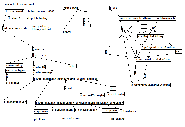
The controls for triggering individual notes were placed into sub-patches. The front facing controls are designed for use with sequencer sub-patches, with the intention of exploring the type of sounds that can be produced. The sequencer sub-patches do not represent any part of the Game Boy’s hardware and serve only as a source of control. Similar extensions of the patch were used to connect PD Boy to a larger game system. This can be seen in the pd osc_in sub-patch. This patch was written to accept and process Open Sound Control (OSC) messages from a Unity driven game and trigger suitable audio.
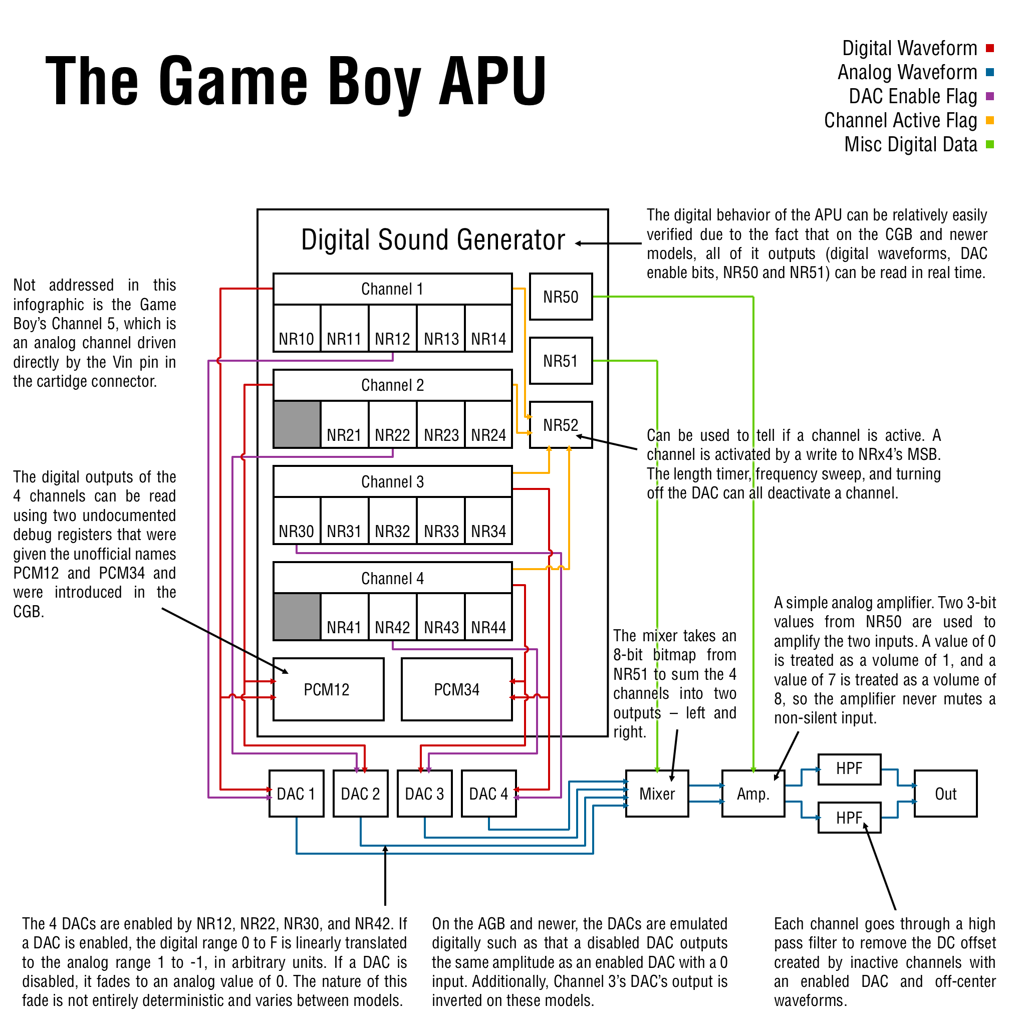
PDBoy seeks to replicate the features and limitations of the Game Boy’s audio system. The APU provides four sound channels controlled through writing particular values to locations in the GameBoy’s memory which are directed to the registers of the APU: a pulse wave generator which can perform frequency sweeps at variable speeds and has access to a linear volume enveloping, a second pulse channel with only the volume envelope, an adjustable waveform channel, and a noise channel.
In hardware, to control each channel requires writing to several registers. For example: controlling the duty-cycle of the first pulse channel requires writing to NR 11; frequency sweep, to NR 10; volume envelope, to NR 12. Registers NR 13 and NR 14 determine the frequency of the output wave and whether the cut-off timer is used. The cut-off timer length is stored in NR 11 (GameBoy CPU Manual). Below is a map of the particular registers which control each channel and the final mix.
Wave Table
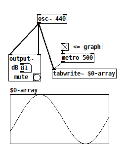
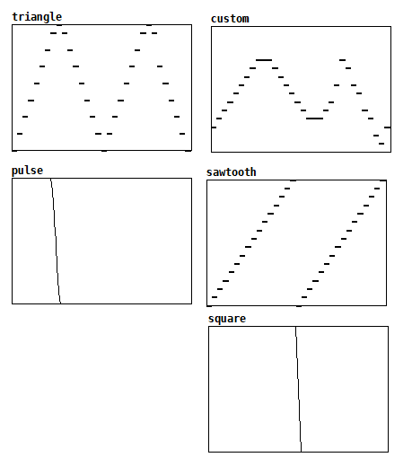
The Game Boy’s third channel allows the creation and playback of a wide variety of waveforms, powered by a built-in wave table. The shape of the waveform is defined through a 128-byte section of memory accessible through 16 registers. Each byte in this memory contains two 4-bit entries in the wavetable. When running. the channel steps through the 32 entries of the wave table generating the tone. Wavetable channel can be used as an additional pulse channel with a nonstandard duty-cycle or to approximate other waveforms such as triangle and sawtooth waves and beyond.
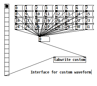
PDBoy represents the wave form using a 32 entry array object. A frequency signal is used to read through the array at the appropriate speed when the channel is enabled and output its values as a signal. I abstracted the process of writing entries into this table by button controls which copy the value of existing arrays into it; analogously this is as if a function was called which would copy the existing wavetable data in ROM and into the memory used by the APU. I present four pre-made waveforms in the patch and controls to write to a fifth custom wavetable that can also be loaded. My interface for constructing custom waveforms allows a user to define the 4-bit table values one at a time, departing from the prior hardware requirement of loading full byte.

Crunchy Noise
The Game Boy’s noise channel utilizes a linear feedback shift register (LFSR) to generate random noise. Shift registers generate a serial output through the shifting of bits internal to the register. Every time the register receives a clock signal the bits are shifted one step. Bits at the end of the register determine the state of the register’s output signal.
Bits          |  XOR  | Signal
1  1  1  0  1   1  0  →
1  1  1  1  0   1  1  →   0
0  0  1  1  1   0  1  →   1
1  0  0  1  1   1  0  →   1
1  1  0  0  1   1  1  →   0
0  1  1  0  0   1  1  →   1
In Pure Data the LFSR took the form of a chain of int objects, each one storing a single integer. When triggered by a metro object, each int passes its stored value one step down the chain. When the last two are triggered, they pass their values into a summation object as well. This value is checked by a select object which checks if they add to one. This will only be the case if one of the values is 0 and the other is 1, mimicking the boolean XOR operation. If they do sum to 1, a 1 integer is loaded into the int object representing the first bit in the LFSR. Otherwise a 0 is loaded.
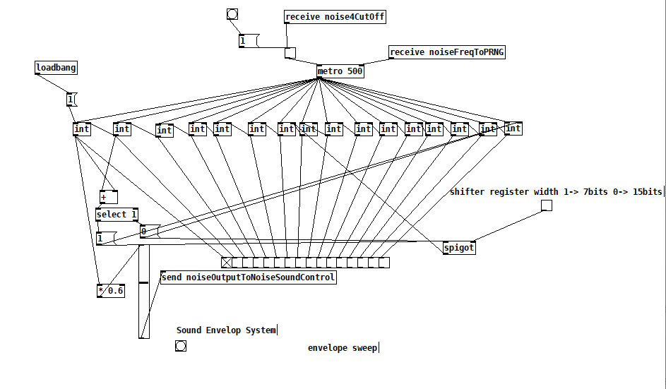
LFSRs generate a noise signal through feeding the result of a boolean operation on two bits in the register back into the register itself. In the Game Boy an XOR operation is used. While noisy, the output of a LFSR is not random and will eventually loop. The Game Boy’s LFSR can be set to a width of 7 bits and 15 bits, changing the length of the noise loop. In PDBoy this choice is presented to the user as a toggle box.
The second mode of control for the programmer is the frequency at which the LFSR is run. This frequency is derived from the CPU clock (4.194304) and two divisors: the shift clock frequency which can range from 2 to 2^14 and the dividing ratio which can be 4, 8, 16, 24, 32, 40, 48, or 56. This provides a range from the startling 524.288 kHz to the slow-burn geiger-counter-esque 4.57 Hz. I present the user of PDBoy with two sets of radio buttons that allow them to select the frequency divider options representing the 3 and 4-bit control values respectively. Within Pure Data this took the form of the chain of objects starting with the highest frequency possible leading into division objects which converted signals from the radio buttons and marked the correct divisors. The final frequency was then converted into fractions of milliseconds to be passed into the metro object which drives the LFSR representation.
The high end of this frequency spectrum proved to be an issue for the computer I was using at the time. I hit the edges of what Pure Data could handle on my machine. The high-level visual programming language was “shockingly” never intended to simulate high frequency clock signals. In order to keep the program from freezing, I included an option to clamp the final calculated frequency beneath 10,000 Hz.
(Not) Controlling for Error
While I was learning Pure Data I used objects that have baked in assumptions. In some cases I chose interface controls with user affordances and in some cases made choices in order to communicate the amount of memory originally allocated for that feature’s control. For example: using a checkbox to indicate whether or not a channel uses a counter to automatically mute itself a set number of clock cycles after it starts playing is analogous to setting the single target bit which controls whether or not that feature is used in the original hardware. Ultimately my decisions were informed through the conflict of exposing the underlying logic of the circuit in a way that could be understood and usability.
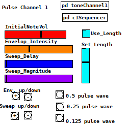
The slider controls are one space when I didn’t think deeply about this conflict as as a result behave anachronistically. I used sliders for their user interface affordance and in the case of setting initial volume failed to convert its value to a proper integer leading to possible states outside the capacity of the Game Boy. Examining the controls now reveals an error; volume which should be represented as an 4-bit integer is now a floating point number.
Another location where I allowed an error to be introduced was the one of the frequency control variables in the noise channel. The shift clock frequency is set using 4 bits, however values 1110 and 1111 are noted as illegal inputs in the documentation. In order to represent what could theoretically be written to the bits for setting this value, I presented a radio toggle with 16 inputs, allowing for these invalid codes to be used for frequency calculation. This was a matter of not looking closely enough at the documentation and instead extrapolating the pattern out.
Conclusion
A strict hardware accuracy lens would identify some major flaws with PDBoys representation: for instance he clock cycles for the various channels are not modeled as coming from a shared system clock and the noise channel must be limited in frequency depending on the computer running the patch, a problem resulting from representing a very low-level hardware system with a very abstract programming language. However, as an interactable tool for communicating to a user the sort of interactions that go into programming audio for the Game Boy’s APU I feel it was a success.
Refences
Altice, Nathan. I AM ERROR: The Nintendo Family Computer / Entertainment System Platform, First MIT Press paperback edition. MIT Press, 2017.
Bogost, Ian, and Nick Montfort. “New media as material constraint: An introduction to platform studies.” In Electronic Techtonics: Thinking at the Interface. Proceedings of the First International HASTAC Conference, pp. 176-193. 2007.
Kummen, Vegard. “The Discourse and Culture of Chip Music Studying the Methods and Values of the Chipscene.” Master’s thesis, Universitetet i Agder; University of Agder, 2018.
Lior Halphon. “Game Boy APU”. Game Boy Pan Docs. https://github.com/LIJI32 Accessed 1/28/2022
Marquez, Israel. “Playing new music with old games: The chiptune subculture.” G| A| M| E Games as Art, Media, Entertainment 1, no. 3 (2014).
Nintendo. Gameboy Development Manual V1.1. 1999, https://archive.org/details/GameBoyProgManVer1.1/page/n81/mode/2up Accessed 1/31/2022
Polymeropoulou, Marilou. “Chipmusic, Fakebit and the Discourse of Authenticity in the Chipscene.” WiderScreen, April 15 (2014).
Tomczak, Sebastian. “Authenticity and emulation: Chiptune in the early twenty-first century.” In ICMC. 2008.